 English
  Spanish
  French
  Russian
  Italian
  German
  Arabic
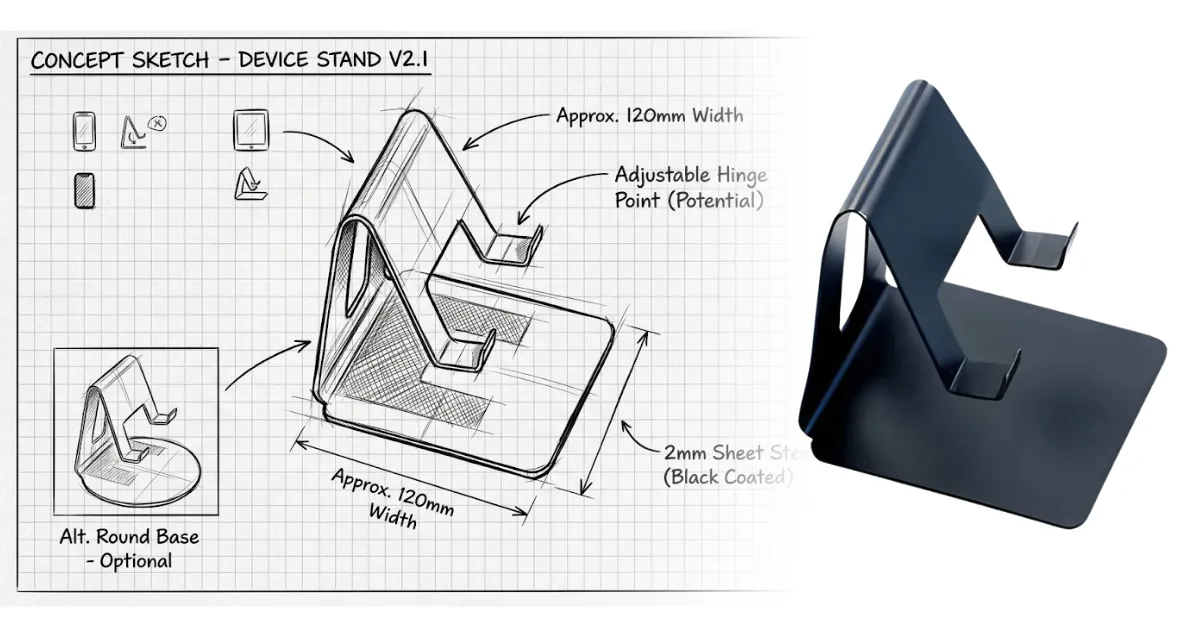
Prototype fabrication uses machining, forming, additive, and molding methods to turn digital models into physical parts. The process from concept to building a product usually involves several steps.
This guide explains how fabrication works, which method best suits each need, and typical timelines and costs.
What Is Prototype Fabrication?
The main purpose of prototype fabrication is to provide useful information and bridge engineering design and manufacturing.
This process turns product sketches into real parts, which are then tested before full-scale production starts.
In this method, you must address several steps, including whether the mechanism works, whether the material meets the required conditions, and whether the parts fit.
Goals mainly separate prototyping from production. Rather than low unit cost, the fabrication process depends on two things: speed and ease of change.
A prototype shop makes a single part, learns from it, and produces a different version the following week; by contrast, a production line makes the same part ten thousand times.
That difference influences every decision. For a few prototypes, shops favor equipment that requires little or no tooling.
Suppose your deadline is five days and you need to test a prototype; you may use low-volume CNC machining to cut the part from solid stock, even if the final version will be injection molded. For only three pieces, you may accept a high cost.
Prototype Fabrication vs Production Manufacturing
Prototype fabrication and production manufacturing often use the same machines. However, they differ in tooling investment, tolerance strategy, and the process’s resistance to design changes.
Treating a prototype like a production part is a major mistake. It can take far longer and cost much more to apply production-level materials and tolerances to the first build, even though you can get the same information from a simpler part.
Types of Prototypes and What Each One Proves
Prototypes come in different types, including proof-of-concept, looks-like (appearance) prototypes, works-like (functional) prototypes, and engineering-grade prototypes, so you can choose the one that suits what you need to test.
Proof-of-Concept Prototypes

Proof-of-concept prototypes test one idea or assumption. For example, a prototype might test whether a sensor can take a reading at a specific distance or whether a latch geometry can hold.
Materials and methods such as foam, cardboard, machined blanks, or breadboarded electronics help build prototypes quickly.
The main goal is whether the idea works; that’s why long-term durability and cosmetics usually don’t matter.
Looks-Like (Appearance) Prototypes

Surface finish, color, branding, and proportion are the main factors that look-like prototypes depend on.
These prototypes are usually CNC machined or 3D printed, then sanded, primed, and painted, and finished with silk screening or applied graphics.
Looks-like prototypes don’t have a working mechanism, but they’re very helpful for photography, user research, trade show displays, and investor conversations.
Works-Like (Functional) Prototypes

Works-like prototypes are another type, designed to demonstrate functional properties such as mechanism, thermal behavior, load path, and electronics.
Rather than appearance, the main focus is function; therefore, during this stage, taped wire harnesses, exposed fasteners, and oversized enclosures are normal.
When structural loads are involved, housings may be printed, while internal brackets may be machined or fabricated as prototype sheet-metal parts.
Engineering-Grade and Pre-Production Prototypes
As the product moves toward manufacturing, engineering-grade and pre-production prototypes use production-intent processes and materials whenever possible, making the test results more useful.
Plastic parts can move to soft aluminum molds and bridge tooling, while metal parts use the actual ship alloy and material thickness.
Before full production begins, such prototypes serve as pilot user trials, regulatory testing, and low-volume production runs.
| Prototype Type | Validates | Typical Methods | Relative Cost | Typical Lead Time |
| Proof-of-concept | A single technical assumption | Foam, FDM printing, hand fabrication | $ | 1–4 days |
| Looks-like | Form, finish, ergonomics | SLA printing, CNC machining, paint, silk screening | $$ | 1–2 weeks |
| Works-like | Mechanism, structural integrity, electronics | Machining, sheet metal fabrication, PCB assembly | $$$ | 2–4 weeks |
| Engineering-grade | Production readiness, compliance | Bridge tooling, production alloys, powder coating | $$$$ | 4–10 weeks |
Prototype Fabrication Process: Concept to First Build
The prototype fabrication process has 7 stages: concept definition, CAD modeling, material selection, selecting your fabrication method, fabrication and assembly, testing, and finally production. It is not a linear process but a loop, with each repetition improving on the previous one.
1. Concept Development and Requirements Definition
You should start by clearly defining the requirements of your prototype parts. For example, “hinge survives 5000 cycles.” Also include what the prototype will not test, like “ignore waterproofing at this stage”.
2. CAD Modeling and Engineering Design

The next step is to design your CAD model. Because you will be improving this prototype CAD model, you need to build it parametrically so that dimensional changes propagate rather than forcing a rebuild.
Apply design for manufacturability while modeling, not after. That means uniform wall thickness for molded parts, generous internal radii for machined pockets, and bend reliefs, plus a correct K-factor for sheet metal design.
3. Material Selection

Material selection can determine not only the properties and behavior of the part but also its manufacturing process. A printed nylon bracket and a machined 6061 bracket have the same geometry and completely different fatigue behavior.
Structural, thermal, and sealing components generally need real metal materials or engineering-grade polymers. If your prototype needs shape and fit testing, you can work with plastics.
| Material | Fits Which Process | Strength / Finish | Relative Cost | Best Used For |
| Aluminum 6061 | CNC machining, laser cutting, and forming | Good strength, clean machined finish | $$ | Brackets, housings, structural test parts |
| Stainless steel 304/316 | Sheet metal fabrication, welding, and machining | High strength, corrosion-resistant | $$$ | Enclosures, food, and medical contact parts |
| Cold-rolled steel | Laser cutting, forming, and welding | Strong, needs a protective coating | $ | Frames, chassis, and industrial machinery guards |
| ABS / PC-ABS | 3D printing, machining, and injection molding | Tough, paintable | $ | Consumer housings, functional covers |
| Nylon (PA12) | SLS printing | Durable, matte, slightly porous | $$ | Complex geometries, snap fits, ducts |
| SLA resin | Stereolithography | Smooth, brittle, UV sensitive | $ | Appearance models, test fit checks |
| Urethane (cast) | Casting from silicone molds | Approximates molded plastic | $$ | Low volume production of 20–100 parts |
4. Choosing the Fabrication Method
Select the manufacturing method from four inputs: geometry, material, quantity, and required tolerance.
Flat parts with bends push you toward sheet metal prototyping. Tight tolerances on mating surfaces push you toward precision machining.
Mixed assemblies are normal and often cheaper. Printing a manifold and then machining only its sealing face is often faster and less expensive than machining the entire part from solid stock.
5. Fabrication and Assembly
Parts arrive from different sources at different times, so plan the assembly sequence before the first part ships. Order fasteners, bearings, seals, and connectors early.
Dry fit everything before final assembly. Test fit exposes interference, missing clearance, and wrong hole sizes while they are still cheap to correct.
6. Functional Testing and Design Revisions
Test against the requirements you wrote in stage one to confirm they are met, uncover design flaws, and record what failed and why. Design validation is only useful if failures are traced to a cause so they do not carry into the final product: a wall too thin, a radius too sharp, a fastener under-torqued.
Batch your changes. Collecting ten fixes into one revision beats issuing ten separate CAD files
7. Transition to Production
Release a complete handoff package: final CAD files, dimensioned drawings, a bill of materials with approved suppliers, finish specifications, and inspection criteria.
Prototype Fabrication Methods & Which To Use?
Prototype fabrication involves several methods, including PCB fabrication, casting, injection molding, 3D printing, CNC machining, and sheet metal fabrication.
For a single assembly, prototypes often combine two or more methods; depending on the geometry, tolerances, and quantity, you can select the appropriate fabrication method.
Precision CNC Machining

CNC machining removes material from solid stock. It is a subtractive manufacturing process that needs no part-specific tooling, such as molds or dies, and it typically holds ±0.005 in. as a standard tolerance and ±0.001 in. on critical features.
CNC Machining also provides material compatibility. It lets you prototype in the same alloys and engineering plastics used in production, so test results translate closely to the final part. However, machined plastics can still behave differently from molded ones.
For sealing surfaces, load-bearing metal parts, bearing bores, and other features where dimensional accuracy matters, this method suits very well.
3D Printing

FDM works well for rough fit checks and jigs, and comparing 3D printing filament properties helps you pick the right material, while SLA produces smooth surfaces for appearance models.
Each printing technology serves a different purpose. FDM works well for rough fit checks and jigs, while SLA produces smooth surfaces for appearance models. SLS and DMLS produce functional parts, and because DMLS needs no tooling, it is a fast route to metal prototypes.
DMLS produces metal components in aluminum, stainless steel, and titanium that can closely represent production parts for validation before scaling. At the same time, SLS creates durable nylon parts with living hinges and snap fits.
Printed parts aren’t equally strong in every direction; they’re stronger along the printed lines and weaker between layers.
This is due to the anisotropic property of printed parts. Part orientation, therefore, affects its strength.
In dimensional accuracy and surface finish, 3D printing falls behind machining, and for simple shapes, metal printing is generally more expensive than machining.
Sheet Metal Fabrication and Metal Forming
Sheet metal fabrication methods include cutting flat material and then bending it into a three-dimensional form. For panels, brackets, enclosures, and chassis, this approach works really well.
Press brakes and lasers support both prototyping and production, so you can make minimal design changes while easily scaling rapid sheet metal prototyping to volume production.
For material thickness and bending, the design must account for it. As a starting point, set the minimum inside bend radius at about one material thickness for mild steel and 5052 aluminum; harder alloys such as 6061-T6 need a larger radius to avoid cracking.
Keep holes at least 2.5 times the material thickness plus the bend radius away from a bend to prevent distortion.
When a single part can’t provide sufficient structural integrity, welding can join several formed pieces.
However, welding heat can distort the surrounding material, so avoid placing tight-tolerance features or critical dimensions near welds.
Laser Cutting and Waterjet

Laser cutting produces flat parts in hours, using a focused beam to cut through sheet stock, with a narrow kerf, typically 0.004–0.015 in. depending on material and thickness.
However, waterjet creates no heat-affected zone and uses abrasive-loaded water. From a flat DXF, both methods can work directly.
For medium-gauge steel, stainless steel, and aluminum, laser cutting suits well, while for thick plates, composites, stone, glass, and heat-sensitive alloys, waterjets suit best.
Injection Molding and Custom Molds
To create plastic parts, injection molding forces molten polymer into steel or aluminum molds.
For early prototypes, hard tooling is more expensive and very slow. That’s why, from a few hundred parts onward, aluminum bridge tooling becomes more practical.
Custom aluminum molds cost a fraction of production steel tooling and take an estimated 2-4 weeks to produce.
Teams choose molding over printing when production-representative plastic properties matter, and at 500+ units, ts the per-part price is lower. Design molded parts with at least 1 degree of draft and ribs no thicker than 60% of the adjacent wall.
Casting

When a mold is filled with liquid material, casting allows that material to cure into the required shape.
This provides a practical middle ground between hard tooling and one-off printing, which suits 20-200 unit quantities.
Urethane Casting
The urethane casting method starts with an SLA-printed master pattern, which is hand-finished and then encased in liquid silicone to form a flexible mold. Once the silicone cures and the master is removed, manufacturers pour liquid urethane resin into the mold and let it harden.
These materials produce parts that mimic rubber, ABS, and polypropylene, and you can customize the material’s hardness and color during mixing.
Vacuum Forming
Vacuum forming heats a plastic sheet until it is pliable, then uses vacuum pressure to pull it tightly over a pattern. The tooling is made from wood or resin, so it is inexpensive and keeps turnaround time short.
For trays, covers, and housings used in equipment and industrial machinery, this vacuum forming process works really well.
Wall thickness may vary; however, the process provides only modest detail.
Electronics and PCB Prototyping
Electronic prototyping has three main stages of development. In the first stage, a breadboard or a development board is used to test basic electronics.
The second stage uses a custom PCB with hand-soldered components. The third and final stage uses an assembled PCBA to production specifications.
3-7 days are required for bare PCB fabrication; however, 2-4 weeks are required for complete assembly with sourced components.
Finishing
During testing, finishing affects prototype performance and how it looks in photographs.
An electrostatically charged dry polymer powder coating is applied to the part and then baked, resulting in an even, hard, corrosion-resistant layer that is tougher than wet paint.
Other surface finishing options include matte textures, media blasting, anodizing for corrosion and wear resistance on aluminum (anodized surfaces are electrically insulating, so use chromate conversion coating where conductivity is needed), plating, and silk screening for logos, indicators, and control labels.
Worked Example: A Consumer Product From Concept to Production
Taking an example of a rechargeable insulated bottle with an electronic temperature-display lid. Over roughly nine months, the product moves from foam models to low-volume production.
Stage 1: Foam Study Models
To compare diameters and grip profiles, the team hand-shapes five foam bodies in two days. Testers handle each version; two advance and three are eliminated, narrowing the exterior profile to two candidates.
Step 2: CAD Model and SLA Appearance Prototype
After modeling the body and lid in CAD, the team SLA-prints both parts, then sands, primes, paints, and silk-screens the logo and display-window graphics.
For photography, user feedback, and early retail conversations, this prototype serves as a realistic model, though it is non-functional.
Step 3: Works Like Functional Build
For snap-fit ribs, the lid housing is SLS printed in nylon. The vacuum-insulated steel body comes from a modified off-the-shelf vessel.
An aluminum retaining ring made by CNC turning secures the electronic stack, while the custom PCB includes a display, battery, and temperature sensor.
Initial testing identifies two problems: the seal leaks under pressure, and the sensor reads high.
Step 4: Design Revisions
To fix the leak, the team deepens the gasket groove to adjust the seal’s compression. To fix the high reading, the team moves the sensor to a thermally isolated pad on the opposite side of the board.
Over two weeks, the team builds and cycle-tests three revised units, and they show no leaks.
Step 5: Engineering-grade pre-production Build
Using the production-grade PC-ABS, an aluminum bridge mold produces 250 lid housings.
The retaining ring becomes a formed and stamped stainless steel part, and the bodies are powder-coated in three colorways.
Then units are drop-tested, subjected to a 100-user field trial, and a 500-hour thermal cycle.
Step 6: Transition to Full Production
For the lid, field data justify investing in hardened steel production tooling. A contract manufacturer takes over assembly, and prototype-only features, such as machined pockets and hand-fitted seals, are replaced with molded geometry.
How Long Does Prototype Fabrication Take?
Depending on the fabrication method, a single prototype can take 1-15 days.
A complete program can take three to nine months across three or four iteration cycles, from concept to a validated engineering-grade build.
Fabrication itself is rarely the main bottleneck. Component availability and design decisions usually have a greater effect on the schedule.
The timeline can be shortened by ordering long-lead hardware and by releasing parts in waves as soon as CAD is frozen.
| Activity | Typical Duration | Common Delay Cause |
| 3D printed parts | 1–5 days | Post-processing and finishing |
| CNC-machined parts | 5–12 days | Shop capacity, multiple setups |
| Sheet metal parts | 5–15 days | Welding, finishing, and hardware insertion |
| PCB assembly | 2–4 weeks | Component lead time |
| Bridge tooling and first shots | 3–5 weeks | Mold trials and adjustment |
| One full iteration cycle | 4–8 weeks | Internal review and decision delays |
Metal Materials VS Plastic Prototyping
Where Metal Wins
Metal parts hold tighter tolerances more reliably, resist creep under sustained load, and dissipate heat. Aluminum and stainless steel enclosures also survive drop and vibration testing that would crack a printed polymer housing.
Metal prototyping has a second practical advantage: the process barely changes with volume. A laser-cut and formed bracket at quantity five uses the same equipment as the same bracket at quantity 5,000, so you can produce parts continuously from prototype through full production without new tooling.
Where Plastic Wins
Plastic handles complex organic geometry, integrates snap fits and living hinges that would need separate metal components, insulates electrically, and weighs far less than even lightweight metals like aluminum and magnesium.
Printed plastic also takes a day, which matters enormously during the prototyping phase.
The cost curve is the catch. Plastic is cheap per part at volume only after you have paid for tooling; below a few hundred units, machined or formed metal often costs less overall.
| Consideration | Metal Materials | Plastic |
| Prototype turnaround | 5–15 days | 1–5 days (printed) |
| Tooling needed for volume | Often none | Mold required |
| Achievable tolerance | ±0.001 in. machined | ±0.003 in. molded |
| Heat resistance | High | Limited |
| Geometric freedom | Moderate | High |
| Cost at 10,000 units | Moderate | Low |
Prototype Fabrication Costs For Metal Materials
Metal prototype parts typically run $75 to $400 each for simple laser-cut and formed sheet-metal components, and $200 to $2,000 each for machined parts, with setup and programming accounting for the largest share of CNC machining cost at low quantities.
Because setup is amortized over the run, the per-part price often drops by 40 to 60 percent between quantities 1 and 10.
Custom CNC-Machined Prototypes
Need a prototype that performs like the final part?
PARTMFG machines prototypes from the same aluminum, steel, and plastic materials used in production, so your test results carry straight into manufacturing.
We hold tolerances to ±0.001 in. on critical features, provide DFM feedback before cutting, and keep lead times short so your iteration cycles stay on schedule.
From a single bracket to an all-volumetric run, one machining partner handles everything. Upload your CAD file today and get a transparent machining quote for your next project.
Conclusion
Prototype fabrication requires iterations that can build on specific questions quickly. Define what you’re testing and choose the simplest method and material that can prove it. Iterate your design in batched revisions by matching the type of prototype and moving towards production gradually.


